

Years ago, I read a book titled “Head First Design Patterns” by Eric Freeman & Elisabeth Freeman with Kathy Sierra & Bert Bates. This book, along with a few blogs and magazine articles, introduced me to software design patterns.
Nothing in the book is especially groundbreaking. I’d been using most of these patterns for years without even knowing they had a name, but it did open a world of software design concepts to which I had previously given very little thought. I was a happy programmer, writing and pushing code to deliver finished products. This book helped me realize that there was more to developing software than just writing code.
From there, my next step was to start exploring UML, or Unified Modeling Language. UML is a way of depicting a software system using symbols to express relationships between various components of a system, with the User being an integral part of the system. UML diagrams are often grouped into two groups, Structural Diagrams and Behavioral Diagrams. Some of the more common ones used include Class Diagrams, Use Case Diagrams and Sequence Diagrams.
Class Diagrams
Structural Diagrams include Class Diagrams, perhaps the most commonly used UML diagram, which are used to depict the various object-oriented classes and their relationships to each other. In this diagram, the various properties and relationships are depicted for a simplistic example of a school’s course registration system. It starts with an abstract base class called Person. The abstract base class contains properties that are inherited by the concrete classes Instructor and Student. Each Person has a one address. Both the Instructor and Student classes have a one-to-many relationship with the Course class, but the Student class also has a one-to-one relationship with the DegreeProgram class, and finally, the DegreeProgram class has a one-to-many relationship with the Course class. Of course, in the real world, the relationships might look a bit different, but for this example, we’ll assume it is as depicted.
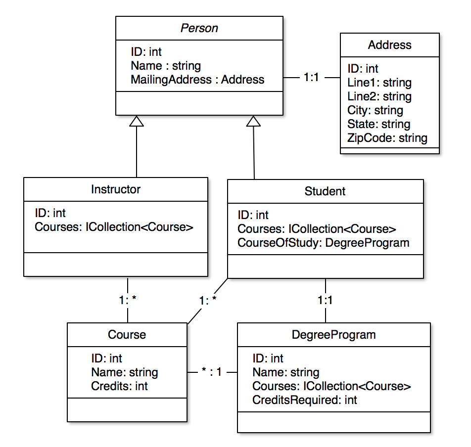
Software classes, or objects, in an Object-Oriented system, can be depicted using UML that clearly define the structure of the system. By the way, it turns out that Class Diagrams also, in their own way, often define the data structure used to persist the data for a software system. The data tables in a database are often modeled directly after the Class Diagrams for the software.
Use Case Diagrams
Behavioral Diagrams are different. They express the dynamic nature of a software system, including how the system responds to User actions, processes that start on a regular schedule, or conditions that trigger actions, and they can depict the flow of information from one system to another. There are several types of Behavioral Diagrams in UML, but my personal favorite are Use Case Diagrams.
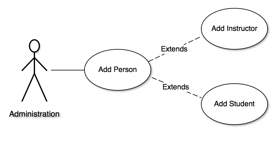
Use Case Diagrams describe what an Actor can do with the software. An Actor can be a User, a Condition, or even a scheduled time for execution. Here we see a simple Use Case Diagram that depicts a User as having the ability to use the system to add a person, either an Instructor or a Student. Naturally this is too simplistic for a real system, but you get the point I think. Each oval represents a specific Use Case.
In the Agile world, we might express Use Cases as User Stories. That’s not to say that you cannot use Use Case Diagrams in an Agile process, just that Users Stories are often a textual representation of a Use Case.
Sequence Diagrams
Use Case Diagrams cannot fully describe the system, but they are very useful for requirements gathering and depicting the actions a system undertakes to perform specific tasks.
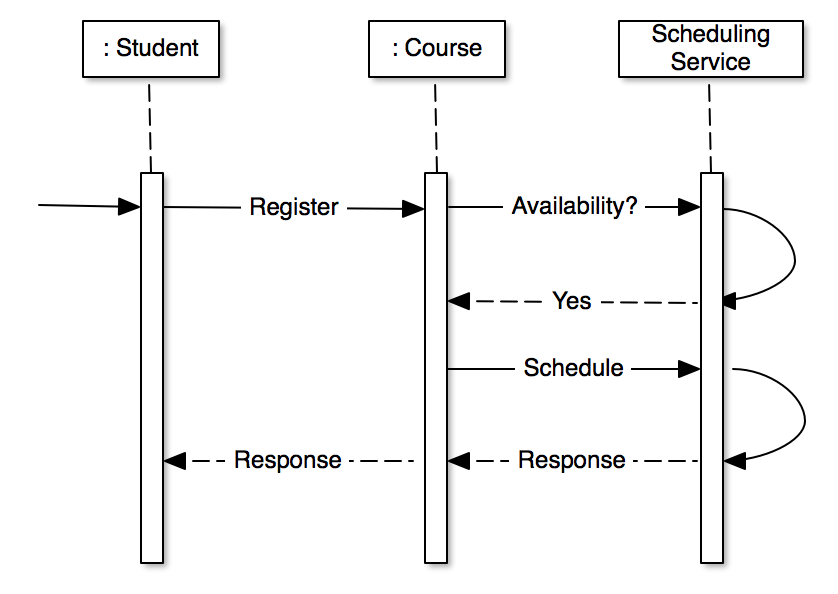
Sequence Diagrams describe the lifetime of a process from initiation to completion. They describe the flow of information from one system to another and are very useful for visualizing which processes and systems are involved in the execution of specific tasks. The following Sequence Diagram describes the individual steps that might be taken when a Student registers for a Course.
UML in Waterfall vs Agile
Some might argue that UML fits in nicely with Waterfall Development, but are not really needed for Agile Development. Waterfall Development is where most, if not all of a system is designed up front and then developed according to the specifications. My personal experiences say that your mileage will vary with Waterfall development. I’ve not seen many Waterfall projects end up the way they were initially designed, because, well, stuff happens. Requirements or budgets might change during the development process, rendering the UML and specifications moot at some point.
Agile Development is where software is designed, developed and delivered in incremental stages, known as Sprints. Most Agile implementations use User Stories to textually describe portions of the application that Use Cases and Sequence Diagrams might describe, but there’s nothing to say that you can’t integrate UML into the Agile process when needed. In fact, UML can be a very useful tool to describe changes or additions implemented as part of an Agile Sprint. It fits in just as well with Agile as it does with Waterfall, and because UML can be drawn by hand on a whiteboard or on paper, it turns out to be quite useful for planning Agile Sprints. Because Agile Sprints are much shorter in duration than a Waterfall design and development lifecycle, the UML generated for a Sprint is not likely to change during the Sprint. If and when requirements change, and they will most assuredly change at some point, new UML diagrams can be created to describe those changes as they are needed.
Tying it All Together
Try using UML in your current or future projects. You might already be using it in some way or fashion, but I encourage you to explore on your own to see how much information is out there and how much it can aid you in designing great software.
There was a time when Microsoft had tools in Visual Studio and Visio that would attempt to reverse-engineer existing code into Class Diagrams, and could take Class Diagrams from Visio and generate code from those diagrams. I don’t know if this functionality exists with current versions of either product, but it would be a nice set of features to bring back if it doesn’t. There are many tools available to create UML diagrams on a computer, but there’s absolutely nothing wrong with creating them the old-fashioned way: pencil and paper or white boards.
Feel free to leave a comment letting me know how you use UML in your development process.